Location
SPN 08 of [The_Cube]: The Agitator
Agitation, stirring the slurry that the biogas digester contains, is crucial to insuring that your digester will produce as much biogas as it can. There are two fundamental reasons for agitation:
- Microbiological: The biogas process is deeply, inherently, and fundamentally symbiotic. Different groups of microorganisms undertake certain steps in the process, such as liquefaction, or the production of less complex molecules from more complex molecules. These groups are all part of the “disassembly” line (the reverse of an assembly line, as in a factory) which is the anaerobic digestion process. It means that very complex substances such as food waste are ultimately turned into very simple molecular end products, such as water, carbon dioxide, and (my favorite) methane. Given the small (indeed microscopic) scale at which these things take place, these hundreds or thousands of different species or groups of micro-organisms must be in intimate contact and well-mixed; because if what one group produces is not taken up by the next group in the disassembly line, then the process stops: by-products accumulate, poisoning the producers of those by-products. (This may happen not just for the digester as a whole, but in small volumes throughout the digester.)
The classic example in biogas arises from the fact that the symbiotic actions of several groups of bitty beasties produce fatty acids as the waste products of their life processes. Those fatty acids— waste products for the previous groups— are food for the methanogens: that is, what a previous group “excretes” is used as a source of energy by subsequent groups. If, for whatever reason(s), the methanogens stop consuming the fatty acids, then the digester will become increasingly acidic, and stop working the way we want it to; it becomes “stuck”. Agitation helps make sure that the waste-products-which-are-also-food (WPWAAF?) are mixed well in the slurry, helping insure that localized high concentrations are diluted, and then seeded with life that can make use of those waste-product/foods. Digestion continues apace.
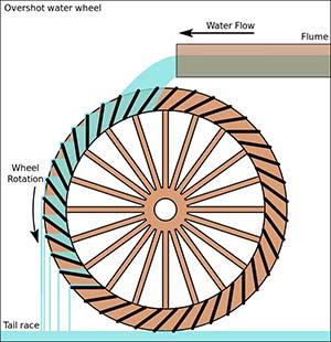
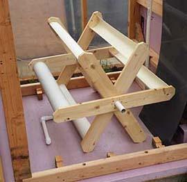
An ‘overshot’ waterwheel. Turn it upside down and fill with gas rather than water, and you’ve got the agitator for [The_Cube]. (Click image to see a larger version.)
- Rheological: That 25¢ word, rheological, means “the study of the way things flow”. If the contents of the digester are not stirred, then what very often happens is that things take the path of least resistance. The slurry coming into the digester will try to find the shortest path to the outlet, and the remainder of the contents will tend to go stale, and stop digesting. This phenomenon is called “short circuiting”. You could think of it as a sort of snake-like stream of slurry finding the quickest path from inlet to outlet, leaving all the other slurry behind.
The consequence of short circuiting is that only some fraction of the digester’s volume will be in active digestion. This happens, mind you, depending somewhat on the design of the digester, in units of all sizes, from small to large, and whether they are above- or under-ground. If you understand the idea of hydraulic retention time (HRT: the average time that slurry stays in the digester before it is pushed out as effluent), then you will realize that as the active or effective volume of a digester is reduced, the actual HRT drops, and one runs the risk of "wash out" where the slurry in that snake rushes out, and does not stay in the digester long enough for the slow-growing methanogens to replace their numbers. The population of necessary microorganisms falls, and, once again, the digester becomes stuck; effective digestion stops.
The cure which prevents these and other bad outcomes is agitation. The relevant question I faced when designing [The_Cube] was: How will this design incorporate agitation?
My answer? First and foremost, because of the nature of poly-panel digesters, we create the container, so we have full access to the inside thereof. Thus, besides the corner bubblers which this design incorporates (see the blog regarding the Gas Collection System, GCS), [The_Cube] makes use of an upside-down waterwheel-type device, the agitator. The basic idea is that the production (or, via pumping, introduction) of biogas can provide the power to turn a wheel and agitate the contents of the digester. Slurry enters [The_Cube] at the front and on the right. The agitator, looked at from the front, rotates clockwise, sweeping slurry down the right, across to the left, up, over, and down, moving toward the back of the digester. Slurry exits [The_Cube] at the back and on the left, completing the spiral. With the corner bubblers clearing out the corners of the cubic interior, the spiralling agitator (God willing and with the generosity of physics) will help keep the contents of a well-built [Cube] in active digestion.
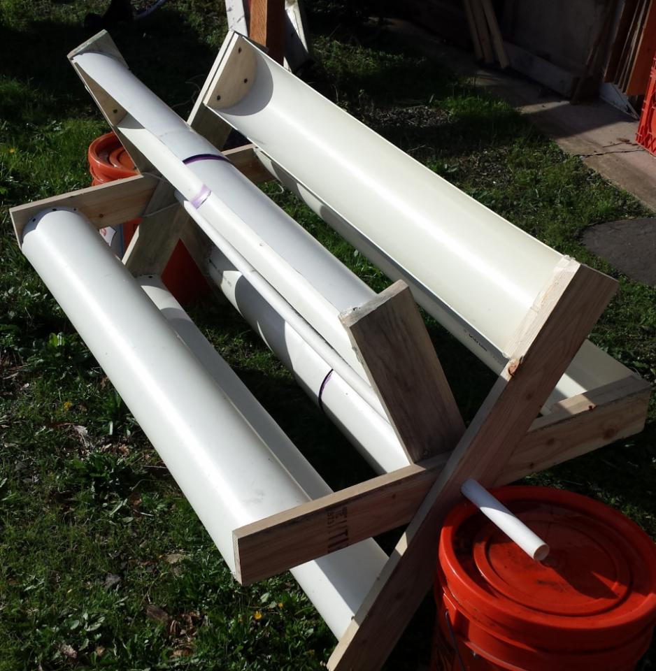
The first agitator that we designed made use of half-circle cut-outs under the ends of the cups (see next image) to hold them in place. That was a fine way to do things, and it will still work. But whether it is an improvement or not, we decided to take a different approach. (Click image for a larger picture.)
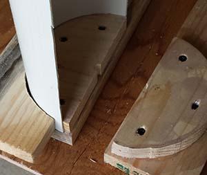
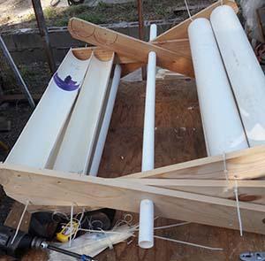
The old-style agitator: struts, half-circle cut-outs, and cups (white pipe). I tested the power of this agitator to turn by putting it on a horizontal axis and gradually filling one cup with water. Repeatedly, at about half to two-thirds full, the agitator turned. When it’s upside-down, the gas being collected will displace liquid, so I figured that same force would be available to push the agitator up and around.
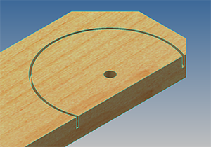
I moved from using wood half circles to creating a slot in the agitator strut which would hold the half-circle end of the cup. Originally decided to try this because I was concerned about screws in the digester rusting; but then I realized that metal could not rust— oxidize— inside an anaerobic digester, where there is no free oxygen. Literature searches subsequently confirmed this. Still, I like this approach. It’s clean.
For the North Carolina Builder’s Workshop, we could not find suitable 4" pipe; only 3" pipe was available. But I had not run tests on cups made from 3" pipe. Would they collect enough gas to power the agitator? I did not know. Then (light bulb!), we realized that we had room along the strut to put two cups on each side. (Some of the images in this blog are of the old-style, single cup agitator because the idea— the “Moose Modification”, as named by the NC team— is very new, so please excuse that.…)
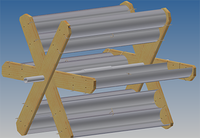
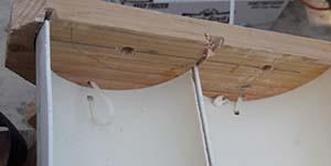
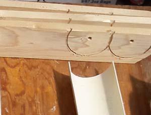
Here we have the agitator, placed in its approximate final position. Notice that it will rotate clockwise. Under its left side, see the pipe? That pipe is slotted. When the gas pump is turned on, recirculated biogas will bubble up into the cups, and the agitator will turn.
But even if you never turn on the pump, the biogas generated in the “shadow” of the cup will fill it (as indicated above; see the big ‘bubble’?), eventually turning the agitator. With two cups, the collection “shadow” is twice as large, so we think the agitator will collect biogas twice as quickly and therefore turn a bit faster. (Click image.)
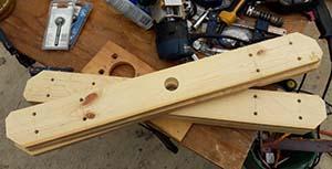
To make the struts, I usually ‘gang’ three lengths of 1x4 together, making the chamfer cuts, the axis hole, the pivot holes and the zip tie holes (to be explained shortly) all at once. Altogether, 6 struts are needed: three ‘right-sided’ and three ‘left-sided’.
Why ‘right’ and ‘left’? If you look at the pipe and strut board above, then mentally turn the strut board over and put it on the other end of the pipe, you will realize that the half-circle will be upside-down. That won't work. So all the struts on one side of the “wings” (two struts plus four cups) will have to be mirror images of the struts on the other side.
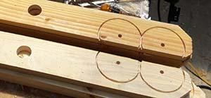
Here’s another view of the strut sets (3 each), and it illustrates as well this idea of right and left. If you mentally put the struts on either end of a half-pipe cup, you can see that they will properly capture both ends.
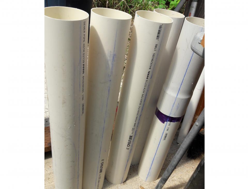
“Cups” for the agitator are made from cut-to-length, 4" dia. PVC pipe, preferably class 200 or ASTM 2729, which is thinner and cheaper than ordinary schedule 40 or sch. 80 pipe. Instead of wasting pieces that are too short (for example after cutting a 10' pipe into several 29" sections), we put the scraps together (right-most pipe), where the “bell” of one too-short piece of pipe has been glued to another too-short piece. Works fine. (Click on image for larger picture.)
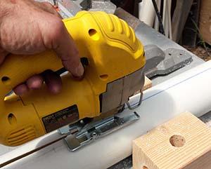
As you can see in the previous picture and this one, I snap a chalk line on the pipes before cutting to length, and then after, I use a jig saw to cut them in half. It works well for me. I weighed each half of every pipe, and found they were very close in weight, meaning they were probably very close to having been cut exactly in half.
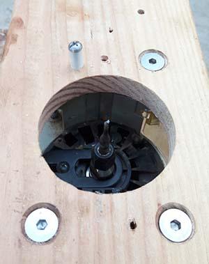
Initially I used a fairly complex jig to make these half-circles, but as explained here, a simpler approach actually works better. Above, you can see that a short bit of 3/8" plastic tube, held in place by a screw, acts as the pivot for the holes we drill in the struts to make the half-circle slots. (For a fuller explanation regarding this jig, visit the link above.)
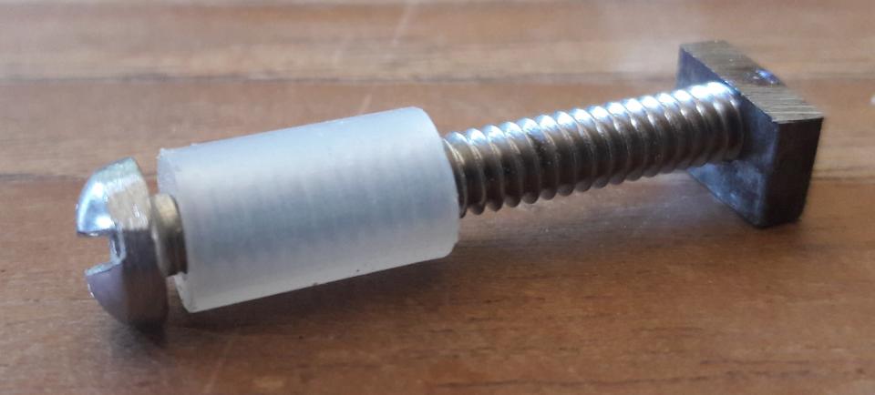
I had to use a grinder to reduce the diameter of the head of the screw I used, because it was larger than the diameter of the pivot hole I drilled in the strut. As well, because of the geometry of my router, I had to grind away part of the nut. Your mileage may vary. (Click to see a larger picture.)
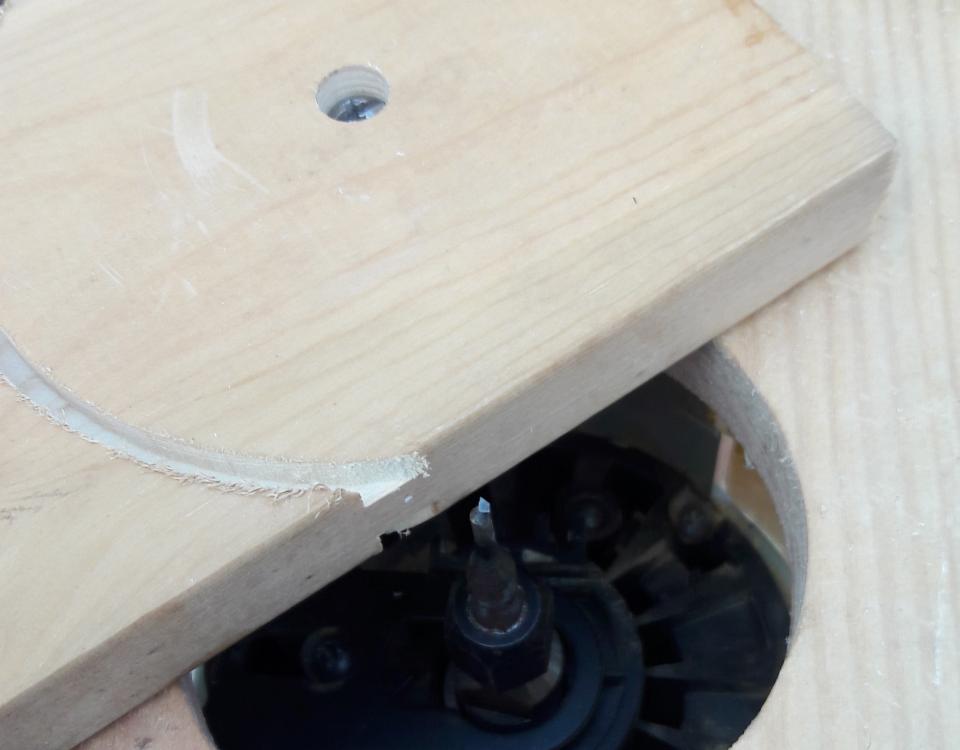
In my testing, I tried one side then the other of the strut board, to insure that the router bit was not going too deep, and to get the radius right. You can see the screw almost sticking out of the pivot hole, and that the board has a half circle slot on both top and bottom, due to my testing. [Click on picture to see a larger image.]
The agitator is made of three “wings”, and they each have to be made in a connected manner, one inside the other. When I started using the half-circle slotting, I was holding the agitator together with nylon fishing line, held taut between the two strut boards. That worked, but not well; it’s hard for one person to put an agitator together this way. Now I use zip ties. That works much better, and it makes putting the agitator together pretty easy.
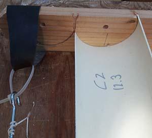
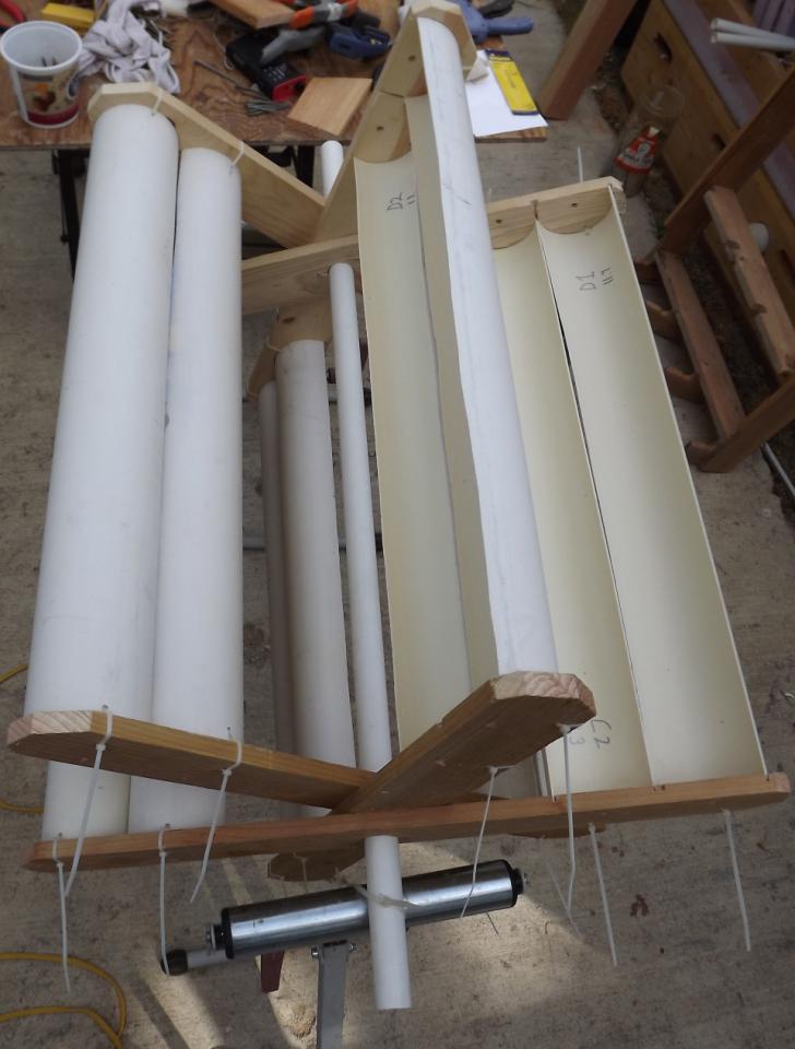
In the 4th picture in this series (above), you can see the zip ties, which are put through holes in the strut boards and pipes. In this picture, you can see on the pipe that I have identified it (“C2”; it’s twin is “C1”) and marked the weight of this cup (12.3 oz). To help put the wings together, I tried using large rubber bands, made from old inner tubes from my wheelbarrows, but I found I did not really need them.
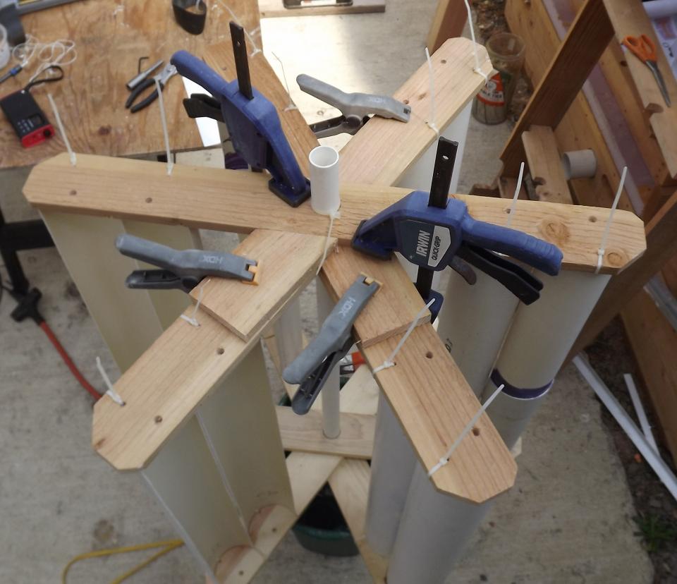
Once the wings are constructed in the somewhat collapsed agitator, they need to be fixed at 60° from one another to complete the build. You can see that I have used (mostly blue) hand clamps to hold the struts absolutely flat and compressed together. As well I used gray clips to hold some jig boards on two of the struts. See the next picture. (And click on this image to see a larger version.)
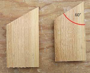
These are the 60° jig boards. Simple, yeah?
Holes are drilled where they will go through all three strut boards, and screws put in. Then the other end is treated the same way. That’s it. Done.
Click image to see a larger picture.