

Location
For the idea for this jig, I am indebted to Scott Mack who attended the Builder’s Biogas Workshop in North Carolina, in June of 2019. He took a router and put a piece of plywood over the bottom, then pegged the agitator strut boards onto a dowel in the plywood. The dowel then became a pivot so he could scribe the half-circles for the agitator cups (which are pipes cut in half) in the agitator struts. (More on all that in the blog about the agitator.)
The new jig I put together for my router was a derivative of that example. I started with a careful examination of my router, which is a Roybi R163.
The jig as made is specific to my router, since, unfortunately, routers vary considerably in the configuration of the screw holes in the bottom of their framework. But hey: no worries. You can do what I did: Take the idea and make it yours, using whatever router you have.
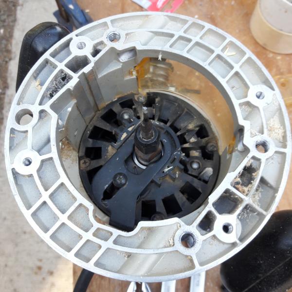
[Click pic for larger image] When I took the plastic base off the bottom of my Roybi router, I could see eight holes, in three sets, as described in the next picture. The big problem was measuring where the holes were accurately enough to reproduce them on my jig board. Briefly, I used vectors, measuring angles and distances, but any approach that works, works.
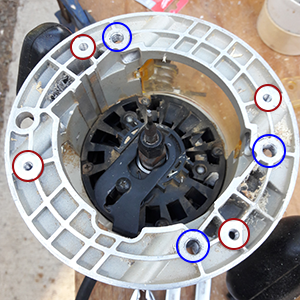
There was one large hole that was not threaded, a set of four small threaded holes (red circles) for the screws that hold the plastic base on the router, and a set of three larger threaded holes (blue circles) that I decided to use to hold the jig board to the router’s bottom.
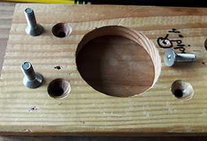
I decided to countersink the holes and to use screws with flat heads and a conical bearing surface. When screwed down, the tops of the screws are below the surface of the board. As far as hole postion, it turned out that two of my holes were right on, and the third was about a sixteenth off. Even so, when I tighten the screws carefully (repeating the same sequence), I am able to have the jig sit in the same position relative to the router’s axis, time after time, so my results when using it are repeatable.
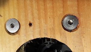
You can see that the hole on the left is somewhat offset, as compared to the hole on the right, where the screw’s head appears well-centered. I remove the plastic base, and put the wood jig board on the router base, then thread the screws into their proper holes and get all three screwed in, but slightly loose. Then I tighten them one at a time. The last screw I tighten is the one that is slightly offset.
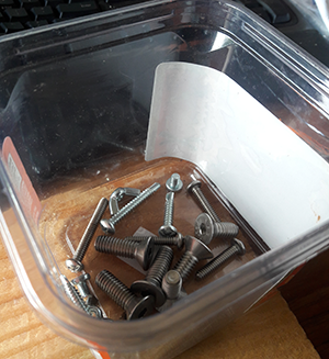
Just by the way, I keep all the small parts pertaining to the router and jig in a single container, and I am paranoid and compulsive about putting any small parts taken off the jig or router in that container, every time. When I know where things are, I save time because I’m not looking for smalll parts, going back to the store to replace what I’ve lost, etc.…
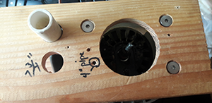
For using the jig to make the pump/heater end caps, which are presently cut out of 3/8" PVC sheet material (with a 3/4"-sized hole in the center to be used as a cutting pivot), I have two choices for a hole in the jig to hold my stub of 3/4" pipe. I chose the upper one (which as shown as a pipe stub in it), which gives me 8" circles. (The other one would give me a 7 3/4" circle.) You can’t see it in this image, but there are also 1/16" holes drilled from the edge of the jig board into each one of the pipe holes. When I put the stub pipe in, I also put a screw into the appropriate edge hole, and the screw holds the pipe stub firmly in place.