

Location
SPN 04 of [The_Cube]: Top square, manufacture and installation
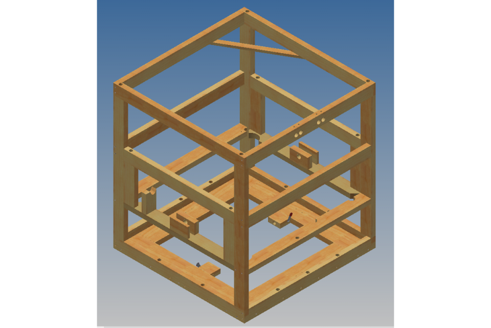
To understand the top square (which holds the four sides of [The_Cube] together at the top; see the top-most wood square in the image to the right), it is useful to understand the internal framework of [The_Cube].
The first thing to say about that is that there must be several billion ways to make use of the central idea of poly-panel digesters— the “sandwich” of wood on the outside, polysty in the middle and wood on the inside— to design the specific container that will be your digester or what-have-you (wine vat? hot tub?).
In the specific case of [The_Cube], we chose to have each side be its own panel. We could have decided to build the internal framework, put the polysty on the outside and hang it in place by putting on the outside wood, but we didn't, for whatever reason. (There is also a discussion of this issue in the blog post about SPN 03: Making the panel left.)
The design of the four side panels starts with the build sequence for the digester. That is, when building [The_Cube], first the panel right goes on the base, then the panel left, top square and the other assemblies which make up [The_Cube], until one puts on the panel back and front (and then finally the panel top). That means two things.
- The first is that the polysty for the panels right and left is only 44" wide, where they sit on a 48" base. That leaves a 2" gap on the front and back. (The polysty is 2" thick as you may know.) The panels front and back are 48" wide, so they fit all the way across the base, and they cover the edges of the panels right and left. (See the blog post mentioned above to see a small video of how that looks in action.)
- The second thing, the one that I'm going to concentrate on in this post, is that the internal frameworks for the panels right and left are designed to allow the internal frameworks for the panels front and back to slide in and be locked together with long screws. That idea can be intuited from the images to the right... (Click on them to see larger pictures.)
As the plans for [The_Cube] detail, each of the five boards that are put together to make the top square need not only to be cut to length, but prepared with pre-drilled holes. Those details are not repeated here.

As described in another blog about a simple jig to keep boards square while building, you should make sure that as you build the top square, it is… actually square. [Click to see larger image.]
Here is a picture of a previous version of the top square, which is quite nearly the same as ther current design, except that we no longer use any of the four corner blocks (cut at an angle; in the middle of the square), nor the plastic for the manifold (the gray shiny piece in this image). The angled bit of wood in the upper left helps support the effluent pipe, and the long 1x6 laying on top of the square is the outside top horizontal support board. That long 1x6 and the 2x4 at the front of the top square both have four holes in their center so that the four pipes manifold pipes can pass from the outside to the inside of the digester. [Click picture for a larger one.]
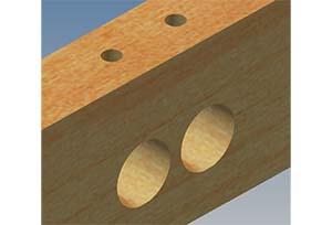
Speaking of the manifold, the top square is designed to enable one to spray urethane into the top of its front-most 2x4 so that it will squish and squirt all around and about, forming (God wiling and with care) a hermetic seal in the wall of the digester, right at the top in the gas space, where leaks might release some of the precious biogas we want to make and collect. The above image is from the Autodesk Inventor model of [The_Cube].

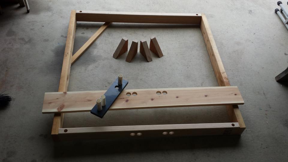
We can also show the same thing actual, which is instructive regarding the difference between the clean, beautiful world of the computer, and the messy, interesting world of actual things. [Click picture for a larger one.]

We place the top square on the top of the inside support frameworks for the panels right and left (where it should nestle down and sigh comfortably), and hold it in place with clamps. After checking square, level, etc. it is screwed in as described in the plans. [Click picture for a larger one.]

This is what the digester will look like (from the top) after the top square is in place. [Click picture for a larger one.]